관련상품
-
상품 상세설명
Product Name:30A 12V 24V DC Motor Controller Relay Board Forward Reverse Control Limit Start Stop Switch for Garage Door Crane Elevator
Wiring Reference Diagram:
General wiring: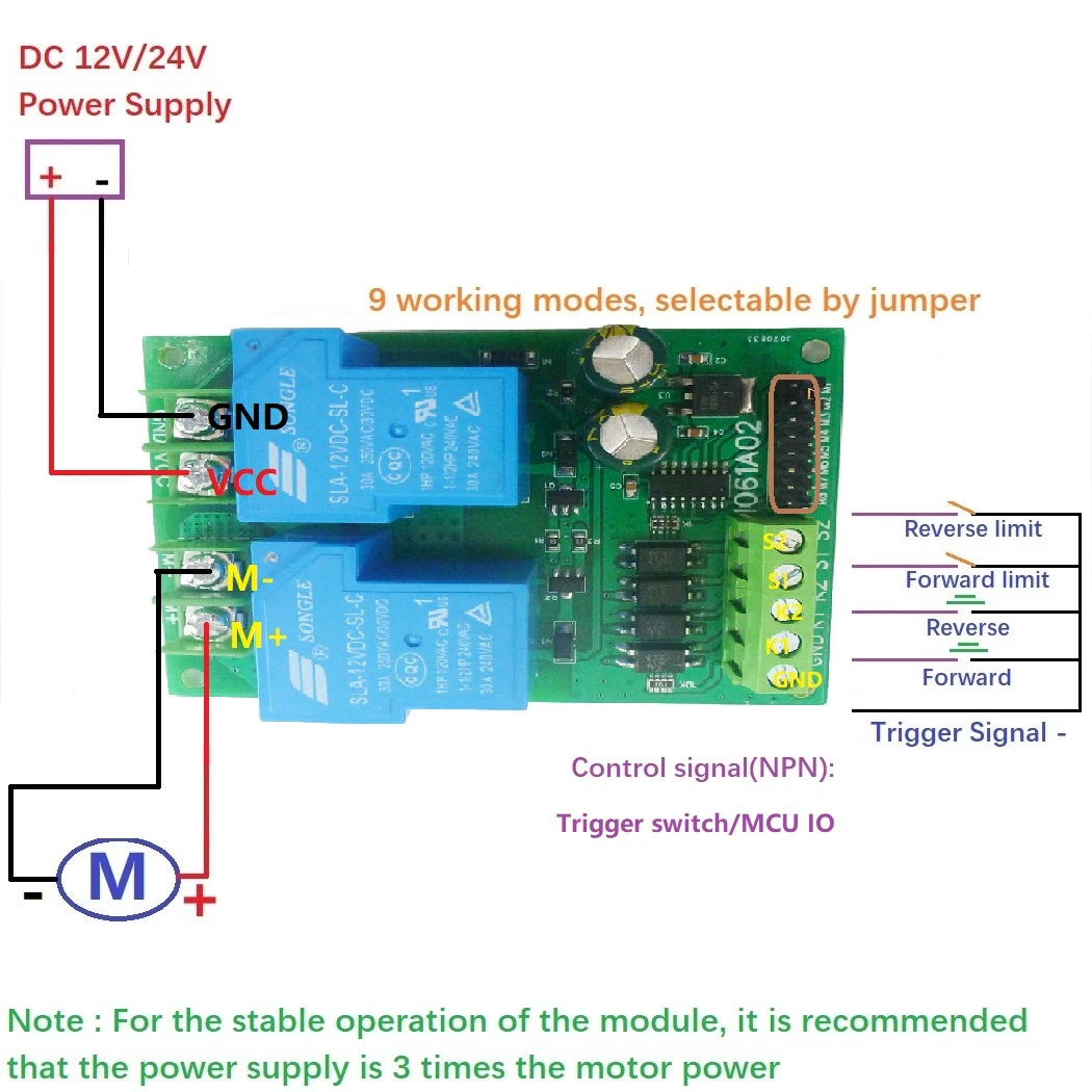
Wiring Diagram 1: Two position (switch) reciprocating
(moving backward and forward in a straight line.)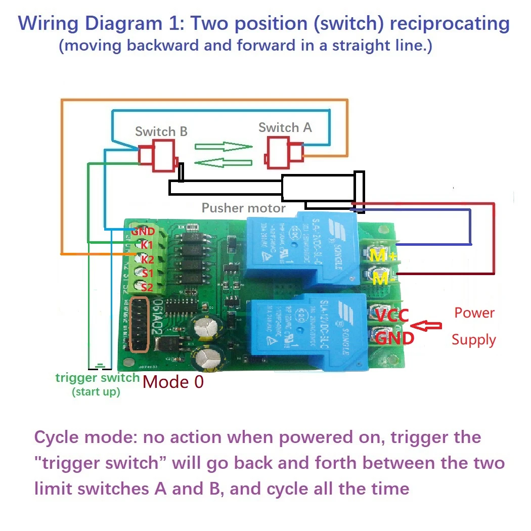
Wiring Diagram 2: Positive and negative start independently, each time running a single pass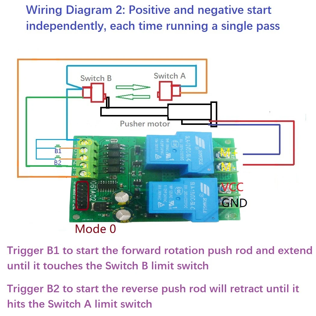
Wiring Diagram 3: Every time you start, run a forward and reverse rotation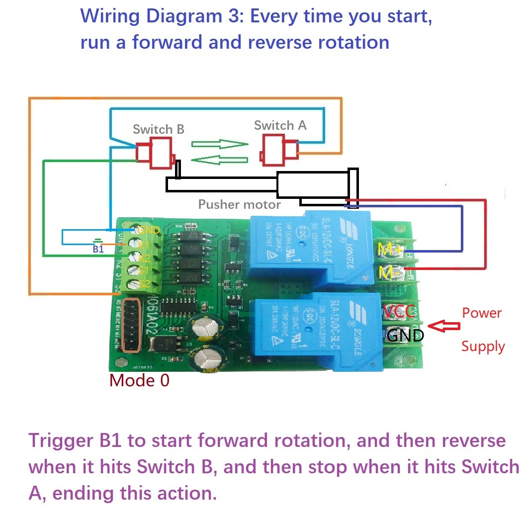
Product Included:
1pcs 30A Relay DC 12V 24V motor forward and reverse controller
Product parameters:
1 Working voltage: DC 12V (12V version) or 24V (24V version) (DC power supply power ≥ motor load x3);
2 Applicable motor: brushed DC motor;
3 Maximum load current: 15A(Relay maximum load 30A);
4 Signal input: active low (NPN);
5 Working modes: 9 optional modes, including momentary, self-locking, etc.;
6 Working current (excluding motor): Quiescent Current: 5MA, Forward or Reverse working current: 70MA
7 Size: 89*62*22mm;
8 Weight: 86 grams.10A relay version, please click here: click here
Pin Description
VCC : Power Supply +
GND : Power Supply -
M+ : Motor +
M- : Motor -
GND : Trigger Signal -
K1 : Forward input control
K2 : Reverse input control
S1 : Forward limit signal
S2 : Reverse limit signal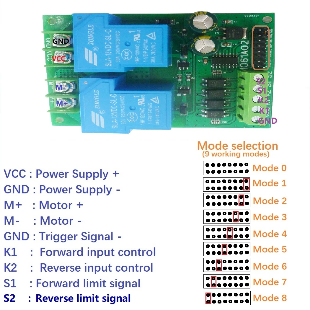
This module has 4 signal input terminals, namely ''K1'', ''K2'', ''S1'', ''S2'', K1 is the forward rotation signal input terminal, K2 is the reverse rotation signal input terminal, and S2 is the forward rotation limit signal Input terminal, S2 is the reverse limit signal input terminal. The signal input source can be selected from micro switch, induction, infrared, metal, remote control and other modules, and can also be controlled by a single-chip microcomputer.
Working mode:
Mode 0 (default) :
Self-locking mode, the signal only needs to be triggered once, and the module self-locking keeps running.
- When encountering a reverse signal during forward rotation, immediately stop for 0.3 seconds and then enter reverse rotation;
- The limit signal has priority, and the forward limit signal will be stopped immediately when the forward rotation is encountered;
- The forward rotation cannot be started when there is a forward rotation limit signal, and the same is true for reverse rotation;
- The forward rotation signal and the reverse rotation signal are valid when the low level, that is, a short-term 0V level (negative power supply), will start;
- The limit signal is normally open; (For example, when the SW1 switch is closed or connected to a low level, the forward rotation cannot be started.)
-Only one limit signal is valid at a time, for example: inputting two limit signals at the same time during reverse rotation cannot stop the motor rotation.
Mode 1 :
The automatic start version of mode 0 adds the power-on automatic start function on the basis of mode 0, that is, each time the module is powered on, it will automatically start forward rotation. This version is more suitable as a motion module between two points, and it will work automatically when the module is powered on.
Mode 2:
Momentary mode. When there is a forward rotation signal, the motor rotates forward; when there is a reverse rotation signal, the motor reverses; when there is no forward rotation signal and no reverse rotation signal, the motor stops; when forward rotation, if there is a forward rotation limit, it will stop forward rotation; During rotation, if there is a reverse rotation limit signal, the reverse rotation will be stopped. Removing the two limit signals will not restore the rotation, and it is necessary to re-input the rotation signal to start the forward and reverse rotation.
Mode 3:
The level-driven mode, similar in function to the H-bridge, operates according to the following logic:
When there is a forward rotation signal and there is no signal at the forward limit, it will rotate forward; when there is a reverse signal and there is no signal at the reverse limit, it will reverse; this version is pure logic type, suitable for single-chip signal input. Pay attention to the forward rotation priority, that is, forward rotation is when both the forward and reverse input meet the conditions.
Pay attention to the real-time nature of the level. For example, when there are signals at the forward and reverse input terminals at the same time, it is forward rotation. At this time, if the forward rotation signal is removed and the reverse signal is retained, it will reverse. The limit input is invalid when the motor is rotating, and the motor cannot be stopped.
Mode 4:
Start/Stop mode, the function is the same as mode 0, only the following function details are different:
If the forward rotation has been started, input the forward rotation signal again, it will stop immediately; if the reverse rotation has been started, input the reverse rotation signal again, it will stop immediately. For example: there is a forward signal >>> forward rotation immediately; at this time, input the forward rotation signal >>> immediately stop forward rotation. Reverse the same.
Mode 5:
The function is the same as mode 0, only the limit signal difference is as follows:
The limit signal is only valid for the current time (the leading edge is valid).
For example, after starting the forward rotation, it will stop when the forward limit signal is encountered. After the stop, although the forward limit signal is still input, the forward rotation can still be started by inputting the forward rotation signal at this time. When the unidirectional start and end points are on the same motion circle, this specification is usually used, for example, press once to make a circle, and press it again to make another circle.
Mode 6:
One-key switch mode, the function is the same as mode 0, only the starting method is different, as follows:
Forward rotation signal input, forward rotation after triggering, reverse rotation after re-triggering, and reverse rotation signal input is invalid. Input the forward rotation signal once to start the forward rotation, and stop the forward rotation when the forward limit has a signal; input the forward rotation signal again, start the reverse rotation, and stop the reverse rotation after the reverse rotation limit has a signal.
Mode 7:
Forward rotation when there is a forward rotation signal input, reverse rotation when there is no signal, and the reverse rotation signal input is invalid and cannot be input together with other signals. During forward rotation, the forward rotation will be stopped if there is a signal at the forward limit; during reverse rotation, the reverse rotation will be stopped if there is a signal at the reverse limit. Only one limit signal is valid at a time.
for example: inputting two limit signals at the same time during reverse rotation cannot stop the motor rotation.
Mode 8:
Self-locking-limit normally closed mode, only the difference of the position signal, other functions are the same as mode 0. The limit signal is normally closed (for example, when there is no signal input to the forward limit, the forward rotation cannot be started, and only when the forward limit signal is input, the forward rotation can be started).
Power Requirements:
The DC motor governor input should be DC power. The power supply can be used but not limited to the following types: switching power supply, DC output transformer, lead-acid battery, lithium battery, solar battery and so on. The power connection wires are connected to the ''VIN'' and ''GND'' terminals respectively, and the positive and negative poles of the power supply cannot be reversed. The power supply voltage range is DC 11-15V (12V version), and it can work normally between DC 22-26V (24V version); DC power requires power ≥ motor power × 3.
Motor Requirements:
IO56D02 is a DC motor controller, and the applied motor should be a brushed DC motor. Connect the motor connecting wires to the terminals of ''Motor+'' and ''Motor-'' respectively. Motor power requirements: the rated power of 24V DC motor is less than 100W, and the limit value is 200W; the rated power of 12V DC motor is less than 50W, and the limit value is 100W.상품정보 제공고시
적용 범위 전압 항목 번호. IO61A02 브랜드 Eletechsup 모델 IO61A02 정격 전류 12V 정격 전압 24V 대외 무역 전용인지 여부 아니오 3C 정격 전압 범위 36V 이하 메인 다운스트림 플랫폼 라자다 주된 판매 지역 아시아 국경 간 내보내기 소스가 배타적인지 여부 예 -
배송/교환정보
- 무통장 입금 계좌 안내

- 342-910021-74704 / 중판(주)